
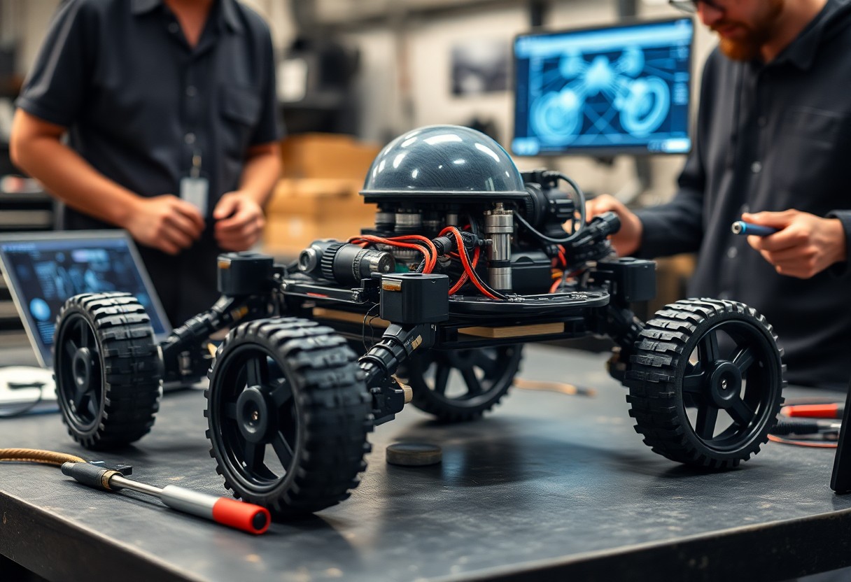
Mobility determines your robot’s capabilities: design modular actuators, apply sensor fusion and adaptive control, and optimize power management and mechanical structure so you achieve stable, efficient movement across diverse terrain.
Kinematic Design and Chassis Architecture
Kinematic layout defines joint arrangement, gait potential, and wheel placement so you can optimize stability, payload distribution, and motion efficiency across tasks.
Comparative Analysis of Legged vs. Wheeled Systems
Mobility Comparison
|
Legged designs give you superior obstacle traversal and variable ground contact control but require complex control and higher actuator density. |
Wheeled systems allow you faster, more energy-efficient travel on smooth surfaces with simpler controls but face limits on rough terrain and step climbing. |
Structural Material Selection for Dynamic Stress
Material selection guides you to balance weight, stiffness, and impact resistance to withstand dynamic stresses during maneuvers and collisions.
Testing and analysis combine finite-element modeling, fatigue testing, and drop trials so you can quantify failure modes and set safety factors; you should compare aluminum alloys for cost and machinability, titanium for fatigue life, and carbon composites for high stiffness-to-weight, while planning joints, corrosion protection, and field reparability to sustain performance over the robot’s service life.
High-Performance Actuation and Propulsion
Actuators combine high-torque motors, lightweight gearheads, and active cooling so you sustain aggressive maneuvers while maintaining thermal headroom and positional accuracy.
Precision Servo Systems and Torque Density
Servos deliver millisecond-level position control and high torque density you tune through winding geometries, gear ratios, and control loops to maximize response while limiting mass.
Power Transmission and Energy Recovery Modules
Geartrains and belts transmit power with chosen ratios and tolerances you balance against friction losses; regenerative drives capture kinetic energy back into storage during deceleration.
Design your transmission by selecting gear topology-planetary, harmonic, or synchronous belts-matching backlash and torsional stiffness to your control bandwidth; include high-efficiency inverters, regenerative converters, and an energy buffer (supercapacitor or battery) sized for peak recapture. Include torque sensors, thermal monitoring, and failure-mode protections so you validate durability under cyclic loads and refine control strategies for safe energy flow.
Sensor Fusion for Environmental Perception
You merge camera, LiDAR, and IMU streams so your robot understands complex environments, reducing false positives and occlusions; see Development of Advance Mobility system for Military Robots for related mobility research.
LiDAR and Depth Camera Integration
LiDAR data fused with depth cameras gives you dense, accurate point clouds for obstacle detection and terrain modeling, improving path planning in varied light.
Inertial Measurement Units for Orientation Tracking
IMUs provide high-rate orientation and acceleration data so you maintain stable state estimation during wheel slips, impacts, or rapid turns, complementing slower visual sensors.
Gyroscope and accelerometer fusion, implemented via extended Kalman or complementary filters, gives you drift-corrected attitude and linear acceleration estimates; adding magnetometer corrections and intermittent visual odometry fixes bounds yaw drift, lets you perform reliable dead-reckoning between camera updates, and smooths control during aggressive maneuvers.
Navigation Algorithms and Path Planning
Path planning algorithms give you optimized routes, balancing speed and stability while accounting for dynamic constraints and energy consumption; incorporate cost maps, kinodynamic planners, and multi-objective heuristics for reliable route selection.
Simultaneous Localization and Mapping (SLAM)
SLAM methods help you fuse LiDAR, vision, and IMU data to produce consistent maps and accurate pose estimates, using loop closure, graph optimization, and uncertainty modeling.
Reactive Obstacle Avoidance in Complex Terrains
Reactive avoidance equips you to detect sudden obstacles and generate immediate steering or gait adjustments through fast perception-to-action loops and prioritized control policies.
You must integrate high-rate sensor fusion, terrain classification, and predictive local planners (e.g., DWA or MPC) so the controller anticipates slopes, loose footing, and moving hazards; tune safety margins and latency budgets to keep reaction times within tens of milliseconds while preserving task objectives.
Control Systems and Stability Augmentation
Control systems refine how you keep the robot upright and responsive, combining sensor fusion, feedback loops, and actuator coordination to reduce oscillations and react to disturbances with minimal delay.
Model Predictive Control for Fluid Motion
Model predictive controllers let you plan trajectories over time horizons, optimizing inputs to avoid jerks while respecting actuator limits and terrain constraints.
Real-Time Balance and Center of Gravity Management
Balancing algorithms help you shift weights and adjust stance in milliseconds, using IMU and force sensors to maintain center of gravity within stability margins.
Sensors and estimator fusion enable you to compute the instantaneous center of gravity and zero-moment point, then distribute torques across limbs to correct drift. You tune filters to handle sensor latency, implement predictive compensation for fast disturbances, and set safety thresholds to trigger recovery behaviors when margins are exceeded.
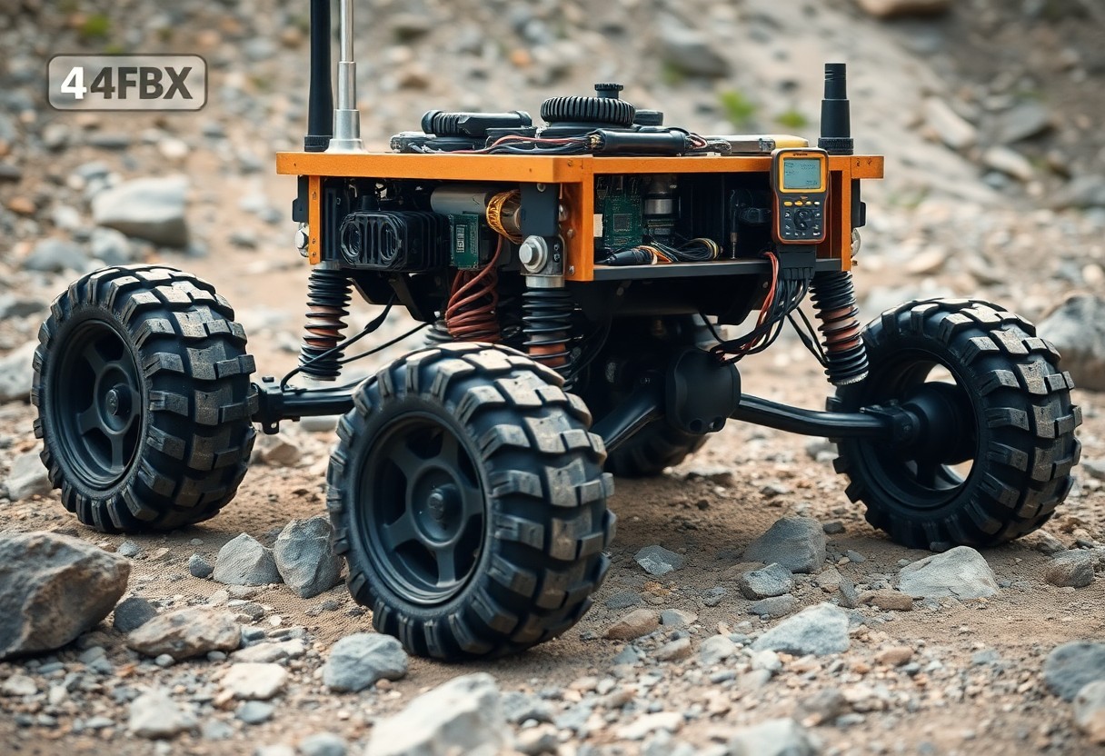
System Integration and Field Testing
Integration of subsystems and progressive field trials let you identify interface mismatches, tune control loops, and verify mobility under real loads; you collect telemetry, iterate mechanical tweaks, and document failure modes to refine deployment readiness.
Software-Hardware Interface Synchronization
Synchronizing firmware, drivers, and middleware requires you to align clocks, manage latency budgets, and implement watchdogs; you validate command-response timing with deterministic tests and log jitter to prevent unexpected actuator behavior.
Performance Benchmarking on Variable Gradients
Testing on variable gradients forces you to record traction, motor current, and speed profiles while adjusting control gains; you map maximum sustainable slope for each configuration and note degradation points for hardware or control tuning.
Analysis of gradient tests requires you to instrument incline sections with load cells and encoders, run repeated ascents across predefined slope increments, and log motor currents, wheel slip, and battery voltage. You compare energy-per-meter and speed retention per percentage grade, identify thermal or traction limits, and update control gains or gear ratios. Iterative modeling then yields slope-performance envelopes and recommended safety margins for deployment.
Final Words
With this in mind you should prioritize chassis, actuators, sensing, and control algorithms to ensure reliable terrain handling, efficient power use, and modular maintenance, allowing iterative testing and clear performance metrics as you build advanced mobility systems.