

There’s a step-by-step method you can follow to design and build a robot drive system that selects motors, gear ratios, chassis layout, and controllers to meet required speed, torque, and handling while ensuring reliable integration and testing.
Evaluating Drive Configurations for Specific Environments
Terrain dictates your drivetrain choice; you must weigh traction, maneuverability, clearance, and power budget to match surfaces and mission profiles.
Comparing Differential and Holonomic Systems
Differential layouts give you simple control and strong traction, while holonomic systems let you move omnidirectionally at the cost of mechanical complexity.
Comparative Overview
| Differential | Holonomic |
|---|---|
| Better straight-line traction | Omnidirectional movement |
| Lower mechanical complexity | Higher control complexity |
| Efficient at speed | Superior maneuverability in tight spaces |
| Common for uneven terrain | Ideal for precise positioning |
Key Factors in Selecting a Drivetrain Layout
Consider load, speed, control complexity, and energy when choosing layout.
- Payload
- Speed
- Control
- Power
After you evaluate trade-offs, choose the simplest drivetrain that meets your mission.
Weight influences motor torque, frame strength, and battery life; you must balance these to avoid overheating and premature wear.
- Torque vs load
- Chassis stiffness
- Battery capacity
After testing under full payload, refine gear ratios and control gains to stabilize performance.
Calculating Motor Torque and Speed Requirements
Calculate required torque and RPM from load, gear ratio, and duty cycle; use inertia, peak loads, and thermal limits to size motors, and consult detailed procedures at Robot Mechanism Design – University Wiki Service so you can verify calculations.
How-to Determine Stall Torque and Payload Capacity
Estimate stall torque by scaling motor stall current with gear ratio, then calculate payload torque from mass and lever arm so you include a safety margin and test starting transients.
Tips for Balancing Performance and Battery Life
Optimize gearing and control so you minimize peak currents while meeting speed; use regenerative braking and current limiting for bursts.
- Select high-efficiency motors
- Prefer moderate gear reductions
The compromise extends runtime with acceptable performance.
Tune motor controller settings, limit continuous current, and profile acceleration so you reduce average draw;
- Implement torque-based control
- Monitor battery voltage under load
The incremental optimizations preserve battery life without sacrificing required agility.
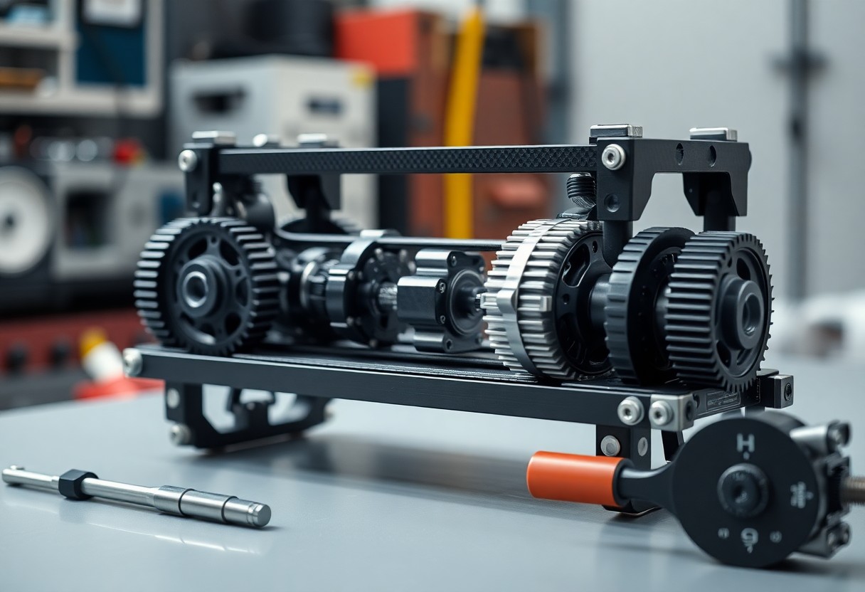
Selecting Power Transmission Components
Choose transmission components that match your motor’s torque and speed, spatial constraints, and operating environment; balance efficiency, durability, and serviceability to minimize losses and simplify maintenance.
Gearing Methods: Belts, Chains, and Direct Drive
Compare belts for quiet layouts and light loads, chains for high torque and shock resistance, and direct drive for minimal backlash and higher efficiency; you should weigh maintenance, weight, and control precision when choosing.
Factors Influencing Mechanical Efficiency
Assess mechanical losses from friction, misalignment, lubrication quality, bearing and gear selection, and excessive clearances; you must tighten tolerances and pick materials to preserve power and extend component life.
- Friction increases with rough surfaces and improper lubrication.
- Misalignment amplifies bearing loads and accelerates wear.
- Knowing your lubrication schedule and tolerances reduces wasted energy.
Optimize tooth profiles, bearing preload, and lubricant viscosity to reduce hysteresis and micro-slip; you should test thermal effects, contamination risk, and duty cycles to define maintenance intervals and tolerances.
- Choose involute gear profiles and appropriate backlash for smooth torque transfer.
- Select bearings rated for combined radial and axial loads and expected life.
- Knowing your duty cycles and contamination levels lets you set sealing and lubrication strategies.
Optimizing Traction and Maneuverability
You must balance wheel grip, weight distribution, and suspension tuning to keep control without wasting power. Experiment with tread patterns, gear ratios, and differential settings to tune both straight-line traction and tight-turn responsiveness within your design constraints.
How-to Choose Wheel Materials and Diameters
Choose wheel compounds and diameters based on surface friction and acceleration needs: softer rubber for better grip, harder for longevity, larger diameters for top speed and obstacle clearance, smaller for torque and agility; match hub design and motor torque to prevent slippage.
Tips for Navigating Varied Terrain
Test wheel pressure, suspension travel, and drive modes before field use: lower pressure and compliant suspension on loose soil, higher pressure on hard surfaces; switch to lower gear ratios for climbing and tighten steering mixing for precise turns.
- Adjust tire pressure for sand, mud, and pavement to tune grip.
- Limit top speed on slick surfaces and engage torque limiting when needed.
- Perceiving subtle wheel slip helps you adapt traction control and driving mode.
Adapt your control algorithms to terrain feedback by using IMU, wheel encoders, and slip sensors to adjust torque split and steering curves in real time; calibrate recovery behaviors for bogging and obstacle escape, and validate autonomous responses at low speed first.
- Log IMU and encoder data to correlate slip events with control actions.
- Tune motor controllers and PID gains for each terrain profile.
- Perceiving changes in vibration and slip helps you refine terrain classification and responses.
Designing the Chassis for Structural Integrity
Chassis geometry and joint placement determine how well you resist bending and torsion; use triangulation, strategic ribs, and reinforced mounting points to keep deflection low under load.
Essential Factors in Material Selection
Material choice forces you to balance stiffness, mass, fatigue life, and cost while considering machinability and corrosion resistance for the intended environment.
- Stiffness-to-weight ratio
- Fatigue and impact resistance
- Machining, welding, and fastening compatibility
After you select material, prototype joints and test at expected loads to validate performance and fastening methods.
How-to Mount Motors and Axles Securely
Mount motors using rigid plates, captive fasteners, and alignment fixtures so you prevent misalignment and vibration that accelerate wear in gearboxes and bearings.
Align shafts precisely, secure couplings with specified torque, press-fit bearings to tolerance, and use retaining rings or safety fasteners where you need permanent retention; verify runout with a dial indicator and recheck mounts after initial test runs.
Implementing Control Systems and Feedback
Control systems let you manage motors, sensors, and feedback loops to keep the drive stable and responsive; implement PID controllers, Kalman filters, and fault detection on your control board to maintain predictable behavior during acceleration, turns, and uneven terrain.
Integrating Encoders for Precise Movement
Encoders provide position and velocity data you can use to close loops, correct drift, and execute accurate trajectories; mount them on shafts, sample at consistent rates, and filter noisy readings before feeding them into your controller.
Tips for Tuning Speed and Directional Control
Tuning PID gains requires iterative testing: increase proportional until you see quicker response, add integral to reduce steady-state error, and temper derivative to limit overshoot; you should log results and trial different payloads to refine values.
- You should use step tests and load variations to observe response under realistic conditions.
- You should apply small gain changes between runs and keep test scenarios repeatable for comparison.
- Recognizing persistent oscillation signals the need for you to lower proportional gain or add damping.
Experiment with feedforward terms and velocity loops alongside PID to reduce lag; tune under both low and high speeds, use encoders for closed-loop velocity control, and establish safety limits to prevent runaway motors while you iterate gains.
- You can measure rise time, settling time, and steady-state error to quantify improvements.
- You can use logged telemetry to correlate tuning changes with real-world behavior across surfaces.
- Recognizing temperature and battery effects helps you schedule retuning and apply compensation dynamically.
Final Words
With these considerations you can choose motors, gearings, and control schemes aligned to your load, speed, and terrain needs, validate prototypes with real-world tests, and iterate until the drive system meets performance, efficiency, and durability targets.