
Most projects succeed when you follow clear steps: this guide shows you how to design the chassis, choose motors and controllers, integrate sensors, and test motion to build a reliable custom robot platform.
Classification of Robotic Platform Types
Platform categories help you weigh mobility, payload, control complexity and environment for your build, enabling targeted component choices and trade-off analysis.
- Wheeled: efficient on flat surfaces with simple control you can implement quickly.
- Tracked: superior traction and off-road capability at the cost of higher mechanical and power demands you must address.
- Legged: obstacle negotiation and uneven-terrain access that require advanced actuation and gait control you will tune.
- Aerial: three-dimensional access and rapid deployment, balanced by strict payload and energy constraints you must plan for.
- This hybrid approach mixes modalities to match mission needs while increasing integration and control complexity you need to manage.
| Wheeled | High efficiency, simple odometry, best for flat surfaces |
| Tracked | Improved traction, good for soft/uneven ground, increased maintenance |
| Legged | Terrain flexibility, complex control, high actuator precision |
| Aerial | Vertical mobility, payload and flight-time constraints, sensor integration |
| Hybrid | Combines strengths of types, raises system integration demands |
Wheeled and Tracked Mobility Systems
Wheeled platforms give you fast, energy-efficient ground travel with straightforward odometry, while tracked systems grant you improved traction and obstacle climb at the cost of added mechanical complexity.
Legged and Multi-Terrain Architectures
Legged designs allow you to traverse irregular terrain and gaps using adaptive gaits, but they demand precise actuators, sensors and advanced control to maintain stability.
Expect to iterate on kinematics, actuator sizing and closed-loop controllers; you should simulate gaits, tune compliance and impedance for terrain interaction, and validate stability with sensor fusion and state estimation before field testing.
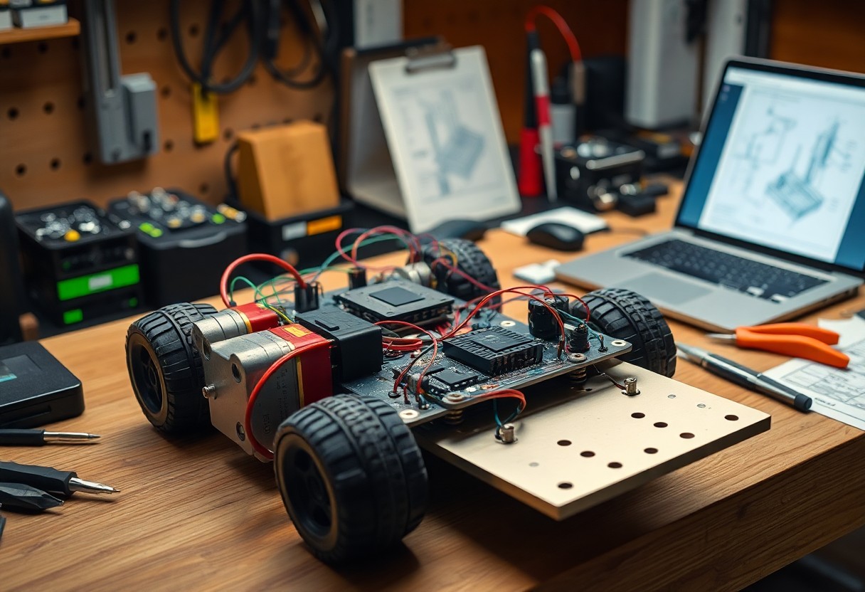
Step-by-Step Assembly Process
| Step | Action |
|---|---|
|
Follow the assembly checklist: mount the chassis, align motors, install sensors, and fasten electronics; test each stage with basic power and motion checks to verify alignment and function. |
|
Framework Fabrication and Component Layout
Fabricate the frame to match your design, position mounting plates and standoffs, and map component locations; you should leave clear service access and arrange mass to keep the platform balanced before final fastening.
Wiring, Microcontrollers, and Logic Integration
Route wiring by function, separate high-current runs from signal lines, and secure the microcontroller where you can access ports; label connections and verify voltage rails before enabling power.
Test individual circuits with a bench supply and multimeter prior to connecting the main battery. You should use a common ground scheme, ferrite beads or ferrite cores on noisy lines, and separate regulated supplies for logic and motors. Program the microcontroller with incremental checks, include watchdogs, and document pinouts and firmware versions for troubleshooting.

Pros and Cons of Custom Platforms
Assessing trade-offs helps you decide if a custom platform fits your project’s goals and resource limits.
| Pros | Cons |
|---|---|
| Tailored performance | Higher upfront cost |
| Custom form factor | Longer development time |
| Proprietary IP ownership | Requires multidisciplinary expertise |
| Optimized payload and power | Component supply risk |
| Scalable to mission needs | Maintenance and support burden |
| Tighter sensor and actuator integration | Harder to meet certification standards |
Performance Benefits of Bespoke Engineering
Optimized actuators and control loops let you tune power, speed, and control fidelity to match mission-specific requirements, yielding measurable efficiency and responsiveness gains.
Resource Constraints and Technical Risks
Planning for longer development cycles, scarce expertise, and firmware complexity helps you weigh whether the anticipated gains justify the added scheduling and budgetary risk.
Budgeting realistic timelines and contingency funds protects your schedule; you must account for multiple prototype iterations, supplier lead times, firmware debugging, integration testing, and certification steps to prevent cost overruns and scope creep.
Professional Tips for System Optimization
Focus on profiling your CPU, power, and I/O to trim latency and inefficiencies; consult resources like Designing And Building A Robot. Assume that you test under real-world loads and iterate fast.
- Profile your CPU and I/O to locate bottlenecks.
- Optimize power and thermal paths for consistent performance.
- Log metrics continuously and trigger alerts on drift.
Implementing Modular Hardware Design
Adopt modular boards and standardized connectors so you can swap sensors and actuators quickly, reducing downtime and speeding upgrades.
Best Practices for Calibration and Testing
Calibrate your sensors with automated routines, validate against references, and run repeatability checks before deployment.
Use temperature-controlled fixtures and traceable reference standards to reduce measurement error, automate multi-point calibrations across operating ranges, and maintain versioned calibration profiles in source control; perform Monte Carlo or repeatability testing, log raw outputs, and set alerts when drift exceeds thresholds so you can roll back updates or adjust compensation quickly.
To wrap up
The guide gives you clear, practical steps to design, source parts, assemble, program, and test a custom robot platform, enabling you to manage risks, optimize performance, and iterate efficiently toward a reliable prototype.