
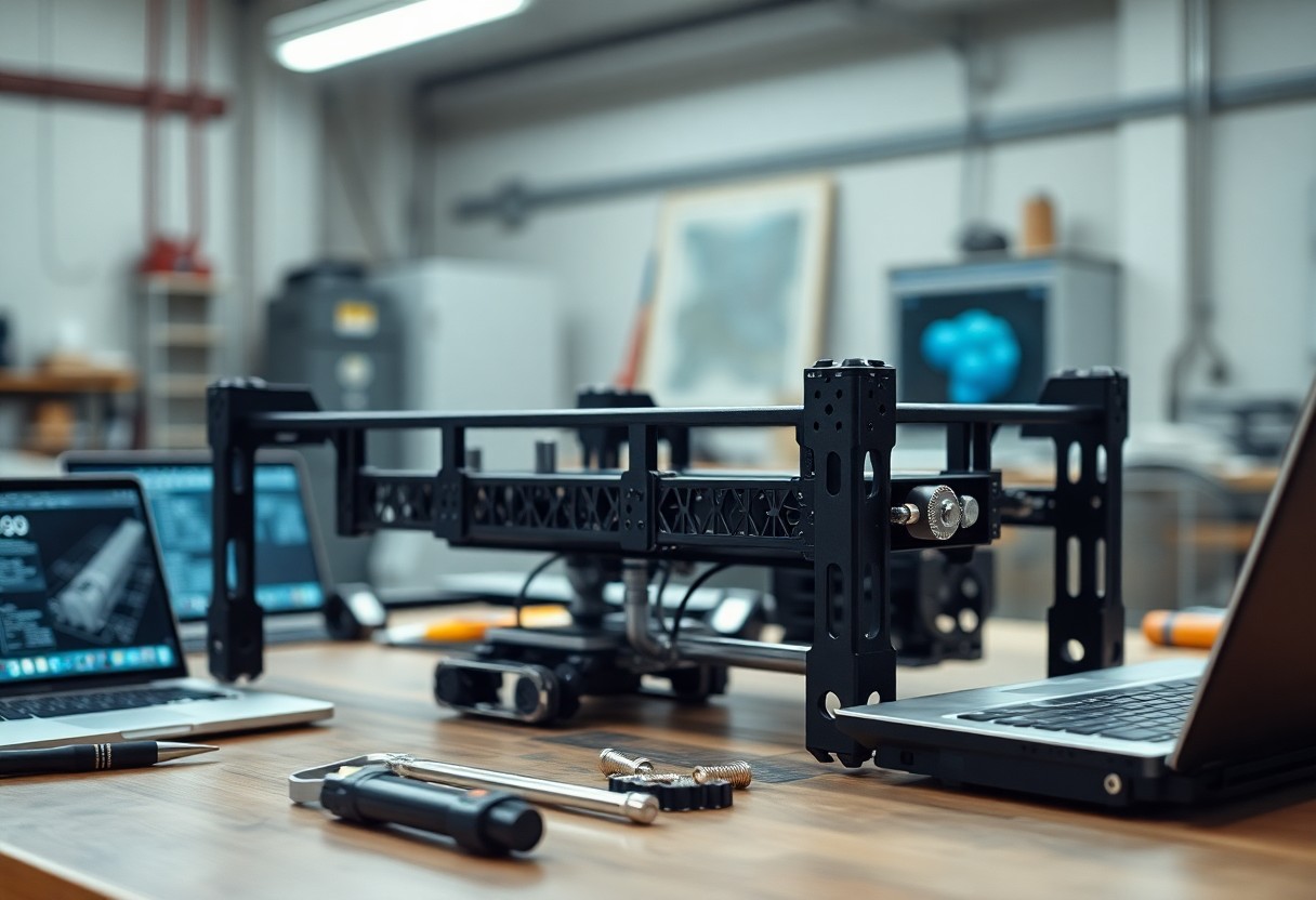
There’s a proven approach you can follow to design and assemble robots with 3D-printed frames, choosing materials and joint geometries and integrating sensors and actuators to balance strength, weight, and function while shortening prototyping cycles.
Material Selection for Structural Integrity
Material choice determines load paths, fatigue performance, and failure modes, so you should prioritize tensile strength, impact resistance, and low creep when specifying filament grades for structural robot parts.
High-Performance Polymers and Fiber-Reinforced Filaments
Carbon- and glass-fiber reinforced filaments give you higher stiffness and heat resistance, yet require print parameter tuning and orientation control to avoid delamination and undersized features.
Analysis of Mechanical Properties and Heat Deflection
Test tensile, flexural, impact, and HDT values on printed specimens so you can quantify anisotropy, thermal limits, and safety margins for operating environments.
Compare printed specimen results across orientations and layer heights, and measure HDT with controlled temperature ramps while logging deformation so you can set conservative service temperatures, choose annealing, and define safety factors for cyclic loads and moisture exposure.
Design Optimization for Robotic Frames
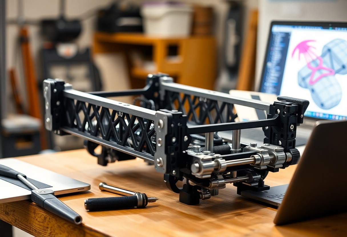
You refine frame geometries, print orientations, and material choices to minimize weight while preserving load paths and maintenance access, using FEA feedback and printer constraints to meet performance targets.
Generative Design and Weight-to-Strength Ratios
Generative design tools let you explore organic lattices and topology-optimized shells that maximize strength for each gram, then translate results into printable meshes and parametric models.
Integrating Internal Cable Management and Mounting Points
Routing internal cable channels and keyed mounting bosses in your prints reduces external clutter, protects wiring, and speeds assembly while keeping connectors accessible for servicing.
Plan cable paths with gentle radii, accessible entry ports, and service loops so you can route harnesses without strain; incorporate printed clips, dovetail rails, and pockets for zip‑ties to secure runs and prevent chafing. You should size bosses for heat‑set inserts or captive nuts to accept fasteners without excess plastic, and test joint orientations and infill to ensure load transfer around connectors. You must allow access for support removal and include modular covers or snap-fit doors so you can inspect or replace wiring without disassembling major assemblies.
Manufacturing Techniques and Tolerance Control
Tolerance in 3D-printed structures affects assembly and function; you should match process, orientation, and post-processing to tolerance budgets. See practical large-part tips at Minibuilders – How to 3d Print Big Structures With Small …
Comparative Analysis of FDM and SLS Technologies
Comparison helps you decide: FDM gives low cost and quick iteration, while SLS offers finer detail, better isotropy, and tighter tolerances for functional parts.
Process Comparison
| FDM | SLS |
|---|---|
| Lower cost, fast prototyping, visible layer lines | Higher cost, smoother surfaces, near-isotropic strength |
| Easy post-processing, wide material access | Better detail for complex geometries, minimal support structures |
Achieving Dimensional Accuracy for Mechanical Fits
Calibration ensures you dial in extrusion, temperature, and compensation so you can print parts that mate correctly; test-fit small coupons before final builds.
You should create calibration prints for common features (holes, shafts, snap fits), measure with calipers, then apply dimensional offsets in CAD or the slicer. Adjust part orientation to reduce unsupported overhangs and warping so you minimize distortion. Consider annealing or light machining for critical fits, and document measured variability so you update design tolerances across batches.
Hardware Integration and Assembly Strategies
Integration of wiring, fasteners, and alignment features reduces assembly time; you should design access points, maintain tolerances for repeatable fits, and plan for modular subassemblies to simplify testing and maintenance.
Implementation of Threaded Inserts and Heat-Set Hardware
Inserts and heat-set hardware provide strong screw engagement in printed plastics; you should select insert type by material and load, control insertion temperature and depth, and validate torque to prevent strip-out or cracking.
Interfacing 3D-Printed Parts with Metal Components
Bridging 3D-printed parts to metal requires you to define load paths, use dowels or shoulder screws for alignment, and add compliant interfaces to absorb stiffness and thermal mismatch.
Consider the mating surfaces: scuff and degrease plastics before applying epoxy or structural acrylics, and test bond strength to the chosen metal finish. Use mechanical backups-press-fit dowels, countersunk screws with washers, or threaded inserts-to carry shear loads. Isolate dissimilar metals with plastic shims or coatings to avoid galvanic corrosion, and add expansion slots or compliant features where thermal mismatch or load concentrations might cause cracking. Prototype critical joints and measure torque and deflection to refine fastener types and engagement lengths.
Post-Processing for Enhanced Performance
Post-processing refines mechanical properties and dimensional accuracy after printing, so you should inspect, remove supports, and verify fit before moving to thermal or surface treatments to maximize part performance.
Annealing Procedures for Crystalline Structure Improvement
You can anneal printed parts at controlled temperatures to relieve stresses and improve crystalline alignment, but monitor time and cooling rates to prevent warping and dimensional drift.
Surface Treatments and Structural Reinforcement Techniques
Surface smoothing, vapor polishing, and targeted epoxy fillets can raise fatigue resistance, and you should apply reinforcement at stress concentrators to extend service life.
Consider combining sanding, bead blasting, and thin resin coatings to seal micro-porosity while adding carbon fiber or fiberglass patches bonded with structural adhesives at load paths so you distribute stresses and reduce crack initiation without adding excessive mass.
Reliability Testing and Validation
Testing confirms that printed assemblies meet load and lifecycle expectations; you should combine bench tests, environmental exposure, and field trials to validate performance under real operating conditions.
Static Load Testing and Stress Distribution Analysis
Static load tests let you apply controlled forces to parts while you map stress distribution with sensors or FEA correlation, ensuring designs carry expected loads without unexpected deformation.
Fatigue Evaluation and Longevity in Dynamic Applications
Fatigue testing exposes printed components to cyclic loads so you can measure crack initiation, growth rates, and expected service life under real motion profiles.
You can accelerate fatigue characterization by using standardized rotating-bending rigs or servo-hydraulic machines that reproduce your robot’s duty cycles. Test multiple build orientations, layer heights, and post-process conditions so you capture anisotropy and defect-driven failures. Analyze S-N curves, mean-stress effects, and run-out behavior; perform fractography to locate initiation sites. Apply cumulative-damage models with conservative safety margins and plan periodic inspections based on statistical life predictions.
Summing up
Following this you should prioritize material selection, print orientation, tolerance control and reinforced joints to ensure structural integrity when building robots with 3D-printed parts; verify designs with load testing, modular assembly and iterative refinement to achieve reliable, maintainable results.