
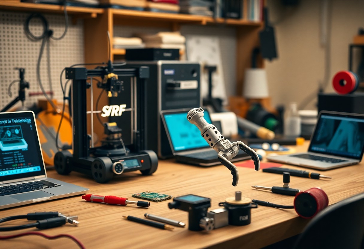
There’s a toolkit of prototyping techniques for robot construction that lets you rapidly test mechanics, iterate control systems, validate sensors, and shorten development cycles with physical mockups, 3D-printed parts, simulation, and modular electronics.
Rapid Mechanical Fabrication
You combine quick frame milling, modular joints, and low-cost printed fixtures to validate kinematics, load paths, and basic function before committing to final materials and finishes.
Additive Manufacturing and 3D Printing Strategies
Printing lets you consolidate assemblies, test complex geometries, and iterate material choices rapidly using tuned infill, multi-material prints, and orientation strategies to optimize strength and weight.
Subtractive Processes and CNC Machining
CNC machining gives you precise tolerances, predictable surface finishes, and strong load-bearing components suited for end-use testing and high-stress prototypes.
Machining demands that you plan stock size, clamp locations, and toolpaths in CAM; you choose roughing and finishing cutters, set feeds and speeds to avoid chatter, design fixtures for repeatable datum referencing, and include inspection steps to ensure dimensional accuracy and repeatability for structural parts.
Electronic Circuit Development
Circuitry decisions determine prototyping speed; you build bench rigs, mock harnesses, and test power domains, consulting resources like What is Robot Prototyping? – Studica to align component choices with system goals.
Solderless Breadboarding and Modular Interfacing
Breadboards let you assemble and swap circuits quickly, test logic and power distribution, and plug sensor modules without solder so firmware and hardware mature in parallel.
Rapid PCB Prototyping and Milling Techniques
Rapid PCB milling and quick-turn fabrication let you verify layouts, check signal integrity, and trial board-mounted components before committing to production.
Detailed rapid PCB work involves selecting substrates, defining trace widths for current and impedance, and choosing between single-sided milling with jumpers or ordering plated-through prototypes; you must control isolation routing depth, pick appropriate end mills, ensure precise double-sided alignment, add fiducials and test points, and plan for assembly-friendly footprints to speed debugging and iteration.
Actuation and Drive System Assembly
Actuation and drive assembly focuses on matching torque, speed, and control interfaces so you can iterate fast with off-the-shelf modules and custom mounts.
Selection of Modular Motor and Servo Systems
Choosing modular motors and servos lets you swap torque and control profiles quickly; test controllers, mounts, and feedback options to refine performance.
Prototyping Transmission and Kinematic Links
Building prototype gears, belts, and linkages with 3D-printed parts lets you validate kinematics and tolerances before committing to machined components.
Test transmission concepts using 3D-printed gears, laser-cut plates, and off-the-shelf belts; you can prototype different gear ratios, coupling types, and bearing placements, then measure backlash, alignment, and efficiency with calipers, dial indicators, and simple torque rigs. Iterate by adjusting tooth profiles, adding idler pulleys, or swapping flexible couplings to control compliance. When geometry and loads are proven, translate critical parts to CNC or injection-molded materials while keeping validated tolerances.
Control Software and Simulation
Control software requires iterative simulation so you can validate algorithms, tune PID gains, and test failure modes before hardware integration, reducing costly physical trials and shortening development cycles.
Virtual Modeling and Digital Twin Validation
Models in a digital twin let you compare expected motion, sensor outputs, and timing against real-world data, enabling earlier fixes and more confident integration decisions.
Embedded Firmware Iteration and Debugging
Firmware iteration uses hardware-in-the-loop tests so you can exercise interrupts, timing, memory constraints, and peripheral interactions before field deployment, lowering firmware-related failures.
You should combine unit tests, continuous integration, on-target logging, JTAG breakpoints, and emulation to reproduce timing bugs, verify watchdog behavior, and iterate safely across firmware revisions.
Power Management and Distribution
Balance your power buses by mapping loads, sizing conductors for peak current, and placing fuses or circuit breakers at distribution nodes to minimize voltage drop and simplify troubleshooting.
Battery Chemistry and Capacity Planning
Choose battery chemistry based on energy density, discharge rate, temperature tolerance, and cycle life; size capacity to meet aggregated amp-hour demand plus a safety margin for your runtime targets.
Voltage Regulation and Safety Circuitry
Implement voltage regulation to provide stable rails for controllers and motors, using switching converters for high-efficiency motor supply and linear regulators for noise-sensitive sensors; include overcurrent and thermal protection.
When selecting regulators, you should prefer switching converters for motor rails and linear regulators for sensitive analog domains; plan thermal dissipation with heatsinks or copper pours. You must place decoupling capacitors close to pins, add current sensing and polyfuses, and include TVS diodes and MOSFET reverse-polarity protection with clear PCB isolation for high-voltage paths.
Iterative Testing and Validation
Testing cycles should be short and frequent so you catch design flaws early; use unit tests, bench trials, and full-system runs to iterate hardware and control logic quickly.
Environmental Stress and Load Evaluation
Stress tests should simulate temperature swings, vibration, dust, and payload extremes so you can quantify safety margins and refine mounting and material selections before field deployment.
Sensor Calibration and Data Fusion Analysis
Calibration routines must align sensor frames and timestamps so you can reduce drift and measurement bias; validate fusion with controlled trajectories and labeled ground truth.
Sensors require time synchronization, cross-calibration, and noise modeling so you can tune filters and data-association rules; you should run repeated trials against motion-capture or high-precision references, analyze residuals, test EKF/UKF and particle filters under varied dynamics, and monitor estimator consistency metrics to expose failure modes and optimize fusion parameters.
Conclusion
Upon reflecting, you see that rapid prototyping, iterative testing, and modular design speed development while reducing cost and risk; prioritize physical mockups, 3D printing, and basic electronics to validate mechanics and controls before scaling.