
You will learn practical steps to design, assemble, and test a modular robot platform, including electrical interfaces, mounting standards, and firmware strategies to mix-and-match sensors and actuators for rapid prototyping.
Core Architectural Principles for Modularity
Design your robot around clear module boundaries, uniform mechanical and electrical interfaces, and versioned APIs so you can swap subsystems without redesigning the whole platform.
Standardized Mechanical Interfaces and Mounting
Mounting points and kinematic locators should be standardized so you can attach modules with repeatable alignment and predictable load paths, reducing custom fixtures and installation time.
Unified Electrical Interconnects and Bus Systems
Wiring and bus choices should provide power, data, and signaling on a common connector schema so you can swap modules, monitor health, and maintain backward compatibility across revisions.
Connections should define power rails, ground returns, signal reference, and common pinouts so you can design modules that plug into any slot. You should pick bus protocols by function – CAN for motor control, Ethernet for high-bandwidth vision, and I2C/SPI for sensors – and include isolation where voltage domains mix. Use power negotiation, hot-plug detection, and fuse-based protection so you can prevent damage and simplify diagnostics.
Power Distribution and Management
Manage power distribution by grouping swappable modules on keyed bus boards with per-rail fuses, current sensing, and hot-swap protection so you can replace hardware without tripping the whole system.
High-Current Quick-Connect Solutions
Use high-current quick-connects like Anderson Powerpole, XT60 variants, or M8/M12 industrial plugs with secure latching and low-resistance contacts so you can minimize voltage drop and allow fast, safe swaps in the field.
Independent Voltage Regulation and Isolation
Isolate voltage domains by giving each module its own regulator or isolated DC-DC converter, preventing backfeed and ground loops so you can run modules at different voltages and protect shared rails.
Design per-module regulation using synchronous buck converters for efficiency, add soft-start and current limit to curb inrush, and implement ideal-diode or hot-swap controllers so you can manage source priority. Instrument each rail with voltage/current sensing for fault handling, include EMI filters and local decoupling to contain switching noise, and plan thermal paths for sustained loads.
Communication Protocols and Data Interfacing
You define physical and logical interfaces, specify timing, framing, and error handling, and standardize message formats so swappable modules exchange data reliably across different buses.
Selection of Robust Bus Topologies (CAN, I2C, SPI)
Choose buses by considering noise immunity, determinism, bandwidth, topology, and node count; use CAN for distributed control, SPI for high-speed local links, and I2C for simple low-speed configuration channels.
Auto-Discovery and Module Identification Logic
Design auto-discovery with unique IDs, version tags, and capability descriptors so your controller maps modules, negotiates power and bus roles, and rejects incompatible devices during boot.
Implement a handshake that reports module ID, class, firmware version, power needs, and pin assignments; include CRC-protected descriptors, timeout-based retries, and a capability mask so the host can allocate resources. You should add role arbitration for duplicates, version compatibility checks, and a signed attestation for security to prevent misconfiguration or malicious modules from joining the bus.
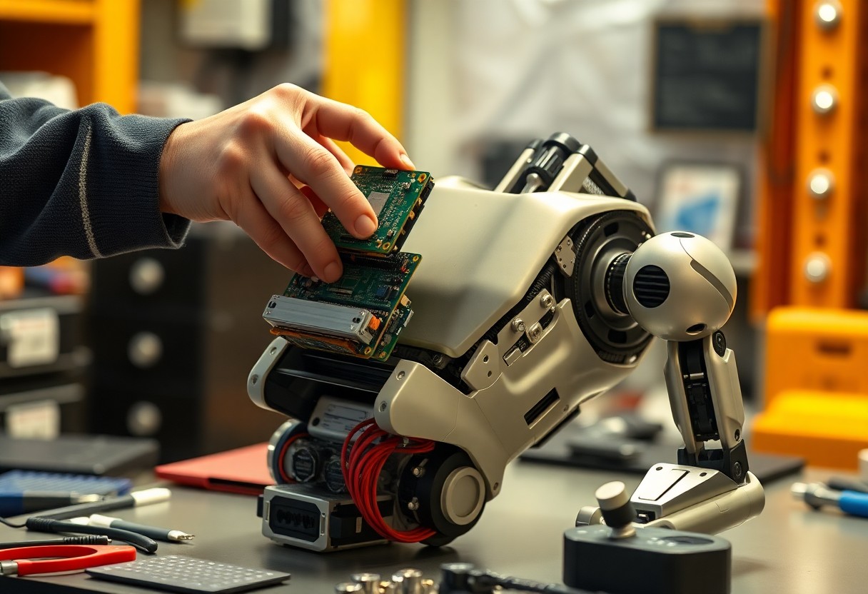
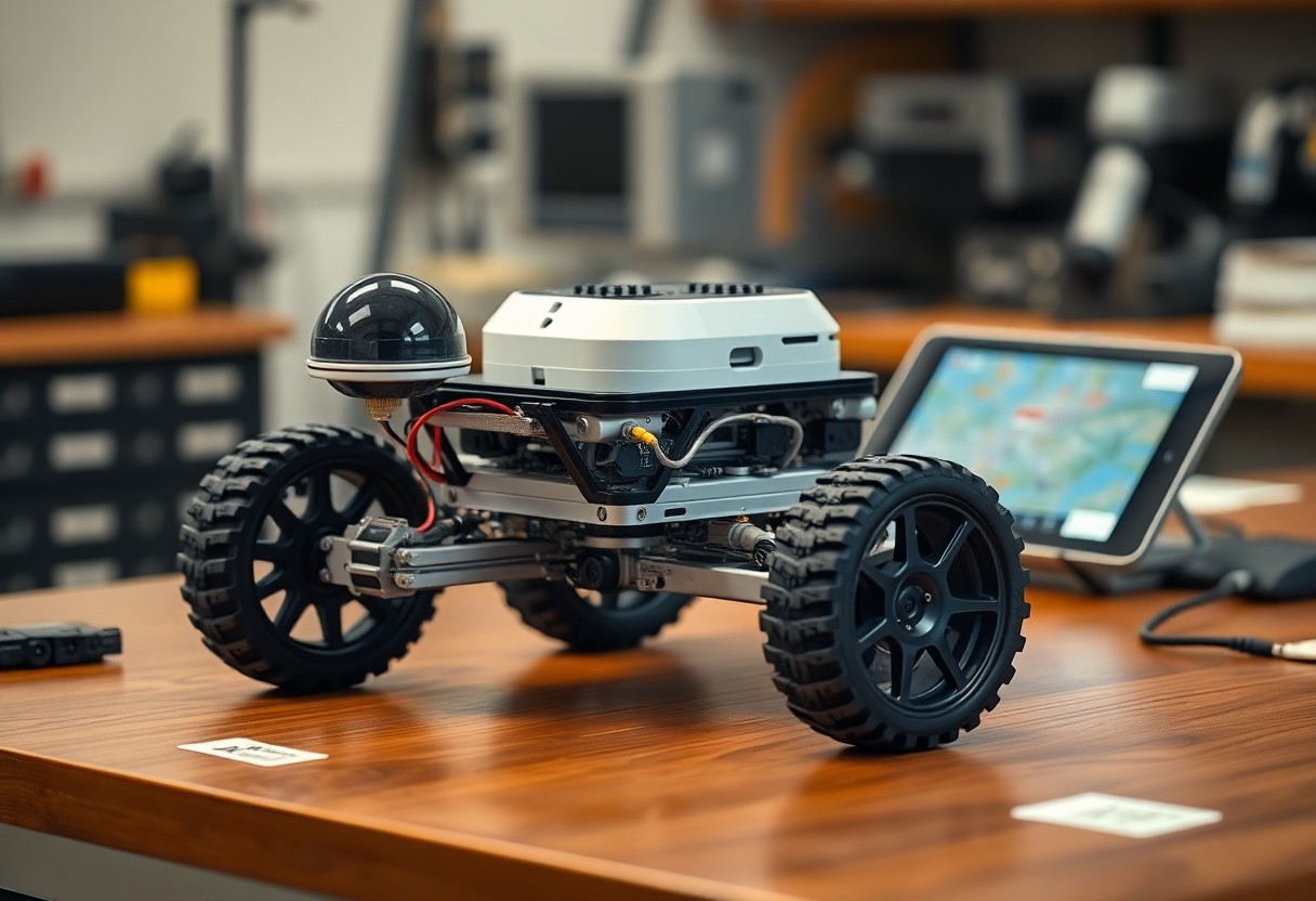
Designing Swappable Actuator Modules
Module designs should prioritize standardized electrical and mechanical interfaces so you can swap actuators quickly; follow connector and mounting conventions and consult resources like Building an Arduino Robot, Part I: Hardware Components for hardware guidance.
Precision Mechanical Couplings and Alignment
Alignment features such as dowel pins and kinematic mounts help you achieve repeatable actuator placement, minimizing backlash and preserving calibration across swaps.
Integrated Motor Control and Feedback Loops
Control electronics should sit on the module so you can plug in power and a communication bus, enabling hot-swaps and consistent wiring.
You should place motor drivers, current sensing, and encoder interfaces on the actuator so loop timing stays tight; run PID locally and expose setpoints/status over CAN or UART, add firmware-level limits and diagnostics to protect hardware, and design a common API so higher-level controllers treat modules uniformly.
Sensor Integration and Environmental Awareness
Sensors must be abstracted into a common bus so you can swap devices without rewriting core logic; expose unified APIs, time-synced readings, and error states to keep perception consistent as modules change.
Plug-and-Play Vision and Proximity Arrays
Vision arrays and proximity sensors should present standardized descriptors so you can hot-swap cameras or LIDAR without breaking obstacle maps, allowing on-the-fly reconfiguration and immediate feedback into motion planners.
Dynamic Calibration for Swapped Components
Calibration routines should run automatically when you insert a module, registering offsets, scaling factors, and latency so sensor fusion remains accurate and control loops maintain stability.
After detection, your system should fetch the module profile, run automated self-tests, gather calibration samples under known poses, compute transform and noise models, store profile with timestamps, and fall back to safe defaults or prompt you if results exceed thresholds.
Software Abstraction and Firmware Management
Software abstraction forces you to centralize versioning, OTA workflows, and signed firmware so modules swap without breaking higher-level logic, while firmware management enforces compatibility and rollback policies.
Hardware Abstraction Layer (HAL) Development
HAL design gives you uniform APIs to query, configure, and control diverse modules, hiding hardware specifics so your application code remains stable when components change.
Real-Time Resource Allocation and Driver Loading
Scheduling and priority management let you allocate CPU, DMA, and IRQ budgets per module, while dynamic driver loading binds drivers only when timing and resources permit.
Configuring real-time allocation requires you to define per-module resource profiles, enforce priority ceilings, and provide fast driver probe paths that validate firmware signatures before binding. Use kernel-level reservations for DMA and IRQ, implement watchdogs and preemptible handlers, and test preemption under load to avoid priority inversion. Provide graceful rollback and clear error reporting if firmware or driver mismatches occur.
Conclusion
From above you can see that designing a robot with swappable hardware modules lets you prototype quickly, reduce downtime, and mix sensors and actuators to match tasks; disciplined interface standards and testing ensure reliable integration and easier upgrades over the robot’s lifecycle.