
Just plan sensors, actuators, control systems, and power; design hardware, implement perception and motion-planning software, and rigorously test so you can build a dependable autonomous robot platform.
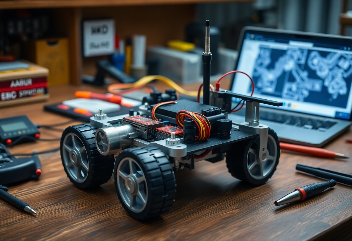
Selecting the Mechanical Chassis and Locomotion
Chassis selection balances weight, payload, ground clearance, modular mounting, and sensor placement; you must match frame stiffness to actuator loads and plan battery and wiring routes for center-of-mass and service access.
Differential Drive vs. Ackermann Steering Geometry
Drive choices affect turning radius, high-speed stability, and control complexity; you can prefer differential drive for tight indoor maneuvering and Ackermann for efficient, car-like handling outdoors.
Motor Torque Requirements and Encoder Resolution
Motor torque must exceed stall torque for inclines and acceleration; you should calculate torque from wheel radius, robot mass, slope, and friction, and pick encoders with resolution matched to your control loop and odometry targets.
Calculating required torque starts with summing gravitational and inertial loads: torque = (m*(g*sin(theta)+Crr*g*cos(theta)) + m*a) * r_wheel. You should estimate worst-case slope, rolling-resistance coefficient, and peak acceleration, then apply a 1.5-2× safety margin. Account for gearbox ratio and efficiency-gearboxes multiply torque and reduce speed-and check motor continuous versus peak ratings against thermal limits. Select encoder CPR so wheel-distance per pulse meets your odometry target, and note that motor-shaft encoders effectively multiply CPR by the gear ratio for per-wheel counts.
Power Management and Distribution Systems
Your power distribution layout must prioritize clean wiring, fusing close to sources, and clear bus segmentation so motors and electronics don’t interfere. You should place current sensors and a central power hub for telemetry, route high-current traces separately, and plan connectors for maintenance to keep uptime and safety high.
Battery Chemistry and Discharge Rate Optimization
Batteries with high discharge C-rates like LiPo or LiFePO4 reduce voltage sag under load; you should match capacity and C-rating to motor peaks, include cell balancing, and monitor temperature to maximize runtime and lifespan without oversizing weight.
Voltage Regulation and Circuit Protection Strategies
Voltage regulators and DC-DC converters should supply stable rails to sensors and controllers; you must add fuses, MOSFET-based switches, TVS diodes, and LC filters to protect against surges and switching noise while preserving efficiency.
Protective design includes selecting synchronous buck converters for efficiency where heat and size matter, placing bulk and ceramic decoupling capacitors adjacent to ICs, and implementing star grounding with separate power and signal returns. You should add soft-start or inrush limiting, place TVS diodes at external entry points, use appropriately rated fuses or PTCs, include bidirectional current sensing for diagnostics, and design thermal paths for regulator and MOSFET dissipation.
The Compute Core: Microcontrollers and SBCs
Balancing power and latency, you assign real-time tasks to microcontrollers while offloading heavy processing to SBCs, aligning compute choices with your robot’s sensors, actuators, and mission profile.
Real-Time Hardware Control via Microcontrollers
Microcontrollers handle sensor polling, PWM, and PID loops with deterministic timing, so you keep motion stable and safe at millisecond scales.
High-Level Processing with Single Board Computers
Onboard SBCs provide the CPU, GPU, and memory you need for SLAM, neural inference, and mission planning, while running ROS or custom stacks.
Consider thermal and power budgets when selecting an SBC; you must weigh CPU/GPU throughput, I/O options (USB, MIPI, GPIO), and OS support to sustain perception and logging under continuous load.
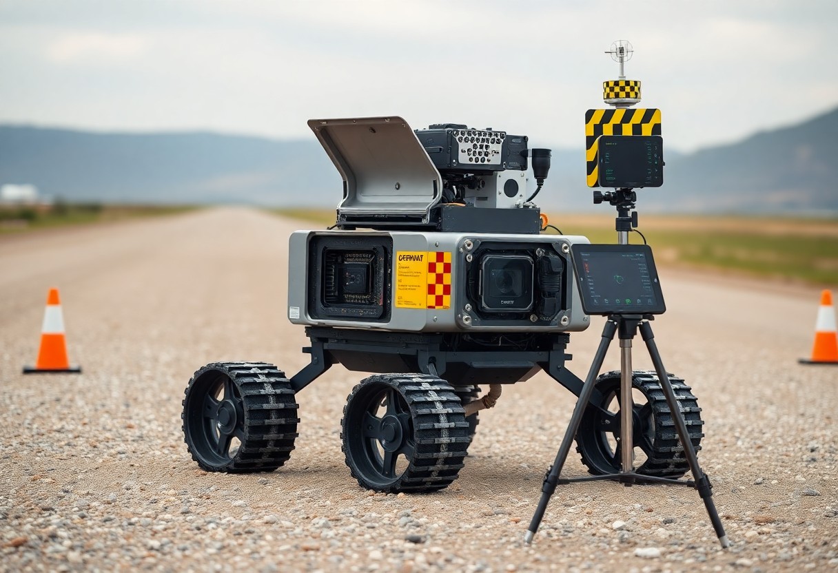
Sensor Fusion for Environmental Awareness
Sensor fusion combines data from camera, LiDAR, IMU, and proximity sensors so you form a coherent scene model for detection and planning, using probabilistic filters to weight noisy inputs.
LiDAR and Depth Cameras for Spatial Mapping
LiDAR and depth cameras give you dense point clouds to build obstacle maps and support SLAM, while depth filtering and voxel or occupancy grids reduce noise and memory use.
IMU Integration and Odometry Correction
IMU integration gives you short-term pose estimates that, when fused with wheel odometry, correct drift via Kalman or complementary filters and detect slip.
Combining IMU and odometry, you should calibrate biases online, model sensor covariances, and run an EKF or factor-graph backend for consistent pose estimation; apply zero-velocity updates and wheel-slip detection to bound drift and maintain reliable localization over long runs.
Software Architecture and Middleware Implementation
Architectural choices define module boundaries, message flows, and real-time needs; you should map sensors, perception, planning, and control into discrete nodes and choose middleware that supports your timing and safety constraints.
Configuring the Robot Operating System (ROS)
ROS configuration requires you to standardize topics, services, and parameters; you should create reusable launch files, use catkin or colcon workspaces, and implement clear node naming and logging practices for debugging.
Establishing Communication Protocols and Data Buses
Selecting protocols and buses affects latency, determinism, and scalability; you should pair CAN for low-latency actuator control with Ethernet or ROS2 DDS for high-bandwidth sensors and provide gateways where needed.
When implementing buses, define message schemas, QoS profiles, and error-handling strategies; you must implement heartbeat monitoring, timestamp synchronization (PTP or NTP), and bandwidth prioritization, and test failure modes with simulated message loss and node crashes to validate safe degradation.
Navigation Algorithms and Path Planning
Algorithms for path planning combine global and local methods so you can plan efficient routes, avoid hazards, and adapt to dynamic environments; see Building Autonomous Robots: A Comprehensive Guide for implementation details.
SLAM Implementation and Localization
SLAM implementations fuse sensor data so you can build accurate maps and track position using particle filters, pose graphs, or graph-SLAM while correcting drift through loop closures.
Obstacle Avoidance and Trajectory Optimization
Obstacle avoidance blends perception and control so you can generate collision-free trajectories with planners like RRT*, A*, or MPC and smooth paths with cost-based optimization.
Advanced obstacle avoidance requires you to integrate lidar, stereo vision, and IMU into a unified costmap, design cost functions that trade off safety and efficiency, select optimizers (MPC, CHOMP, or TrajOpt) that meet your latency budget, and validate in simulation before iteratively tuning controllers on hardware to handle cluttered, dynamic scenes reliably.
Final Words
Following this, you should integrate sensors, open-source software, and modular hardware to build an autonomous robot platform that aligns with your objectives; test extensively, iterate on control and perception, and maintain clear documentation to sustain long-term performance.