Most designs focus on low center of gravity and wide wheelbase; you must optimize frame geometry, material choice, and mounting points to minimize tipping, control flex, and distribute mass for predictable handling across varied terrain.
Material Selection for Structural Rigidity
You must weigh stiffness, weight, cost, and manufacturability when choosing frame materials to ensure maximal rigidity without excess mass.
Comparing Aerospace-Grade Aluminum and Carbon Fiber
Aluminum offers predictable machining and lower cost, while carbon fiber delivers higher stiffness-to-weight; you choose based on budget, fabrication skill, and target mass.
Material Comparison
| Aerospace Aluminum | Carbon Fiber |
|---|---|
| Density: ~2.7 g/cm³ | Density: ~1.6 g/cm³ |
| Modulus: ~69 GPa | Modulus: 70-200+ GPa (grade dependent) |
| Cost & machining: Lower; easy to machine and join | Cost & fabrication: Higher; requires layup, tooling, or autoclave |
| Fatigue resistance: Predictable, damage-tolerant | Fatigue resistance: Good but sensitive to impact and delamination |
| Thermal expansion: Higher CTE | Thermal expansion: Low and tailorable |
| Damping: Lower inherent damping | Damping: Higher inherent damping |
Vibration Damping Characteristics of Composite Materials
Composites typically provide better inherent damping than metals, so you can reduce frame resonance by selecting weave, resin, and core materials.
Layering ply orientations and adding viscoelastic or foam cores let you tune modal damping and move resonant peaks away from motor and gearbox harmonics. You should perform modal testing on representative coupons and iterate fiber volume, resin system, and ply balance to meet damping and stiffness targets without adding unnecessary mass.
Geometric Design and Center of Gravity
Geometry dictates how you place components to keep the center of gravity within the support polygon; position heavy elements near the geometric center and slightly forward for better dynamic stability.
Lowering the Vertical Mass Distribution
Shift heavy components downward and mount batteries, motors, and controllers as low as practical; use standoffs and recessed trays so you reduce your robot’s roll and pitch susceptibility.
Optimizing Wheelbase and Track Width for Balance
Adjust wheelbase and track width to expand your support polygon; widen track for lateral stability and lengthen wheelbase to resist pitching while keeping maneuverability acceptable for your application.
Consider trade-offs: widening track lowers tip risk but increases chassis width, affecting clearance and tight turns. Lengthening wheelbase reduces pitching but raises turning radius and sensitivity to uneven ground. You should calculate the CoG projection against wheel edges under expected accelerations, prototype with adjustable mounts, and iterate until static and dynamic tests confirm safe margins.
Advanced Joinery and Fastening Techniques
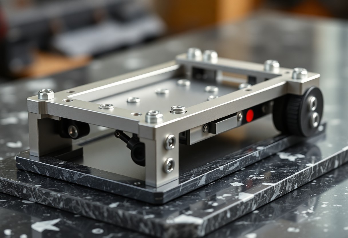
You should prioritize mating surface preparation, correct fastener grade, and proper preload to prevent loosening; combine mechanical joints with structural adhesives where shear distribution is needed, and use captive fasteners or countersinks to maintain precise alignment under load.
- Use hardened bolts with controlled torque and locking methods.
- Apply structural adhesives at shear planes to share loads.
- Install threaded inserts for repeated assembly in composites.
- Stagger fasteners and add dowels for shear-transfer at joints.
Joinery Overview
| Technique | Primary benefit |
|---|---|
| Bolted joints | Disassembly and field servicing |
| Welded joints | Maximum stiffness and reduced part count |
| T-slot framing | Reconfigurability and easy fixturing |
High-Stress Points and Gusset Reinforcement
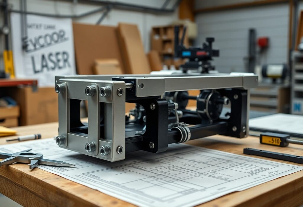
Reinforce high-load intersections with triangular gussets, full-bearing welds or bolted plates so you spread forces and reduce bending; place gussets where bending moments concentrate and use matching thickness to avoid stress risers.
Precision Welding vs. Modular T-Slot Systems
Compare precision welding for permanent, stiff joints with T-slot systems that let you reconfigure and service components; choose based on expected cyclic loads, maintenance access, and geometry stability you need.
Welding gives you superior stiffness and fewer components, but you must manage thermal distortion, qualified procedures, and post-weld inspection to maintain alignment and fatigue life; T-slot framing lets you iterate designs quickly, replace damaged members, and fine-tune bracing without full disassembly, making it preferable when prototypes or frequent changes are expected.
Component Placement and Weight Distribution
You should place heavy modules low and centered to lower your center of gravity and reduce tipping while keeping wiring runs short for stability and serviceability.
Symmetrical Layout for Lateral Stability
Arrange components symmetrically across the centerline so lateral forces cancel, keeping mass balanced during turns and reducing unpredictable roll.
Strategic Mounting of Heavy Actuators and Power Cells
Place heavy actuators and batteries close to the centerline and as low as possible, using reinforced mounts to handle torque and protect connections.
Secure actuators on bulkheads or composite plates aligned with gear axes to prevent binding, use staggered mounting pads to spread loads, isolate batteries with foam or silicone mounts to absorb shock, and route power and motor leads to minimize lever arms that amplify impacts.
Prototyping and Structural Testing
Prototype iterations let you test joint layouts and mass distribution quickly; pair simple rigs with modular parts and consult How to Build a Powerful Robot! : 10 Steps for hands-on techniques.
Stress Analysis Using Finite Element Methods
FEA lets you predict stress concentrations and iterate cross-sections so you can mitigate failure points, validate material choices, and optimize plate thickness before committing to fabrication.
Real-World Load Testing and Deflection Measurement
Bench tests let you record deflection under defined loads, compare measured curves to FEA predictions, and adjust bracing, fasteners, or component locations to meet stiffness targets.
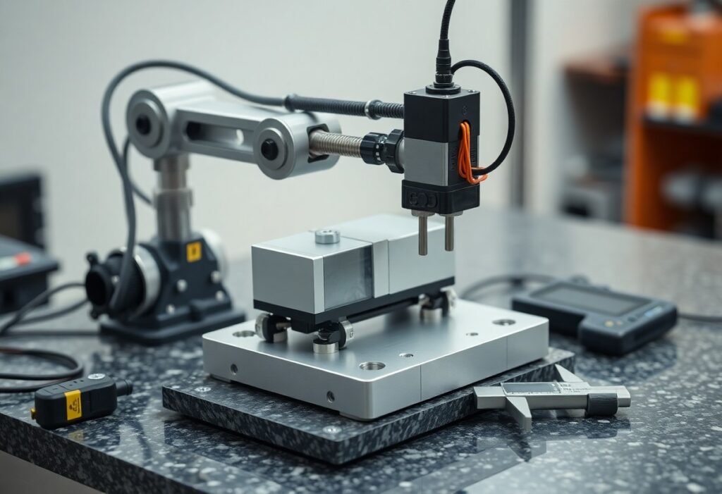
When you set up load tests, use stiff fixtures, calibrated weights or hydraulic actuators, and high-resolution displacement sensors (dial indicators, LVDTs, or laser gauges); record multiple loading cycles, map deflection across key members, and log data to quantify stiffness, hysteresis, and permanent deformation so you can refine bracing, welds, and material selection.
Summing up
With this in mind, you should prioritize a low center of gravity, a wide stance, stiff joints, and balanced load paths when designing a custom robot frame; iterative testing and adjustments will secure long-term stability and reliable performance.