
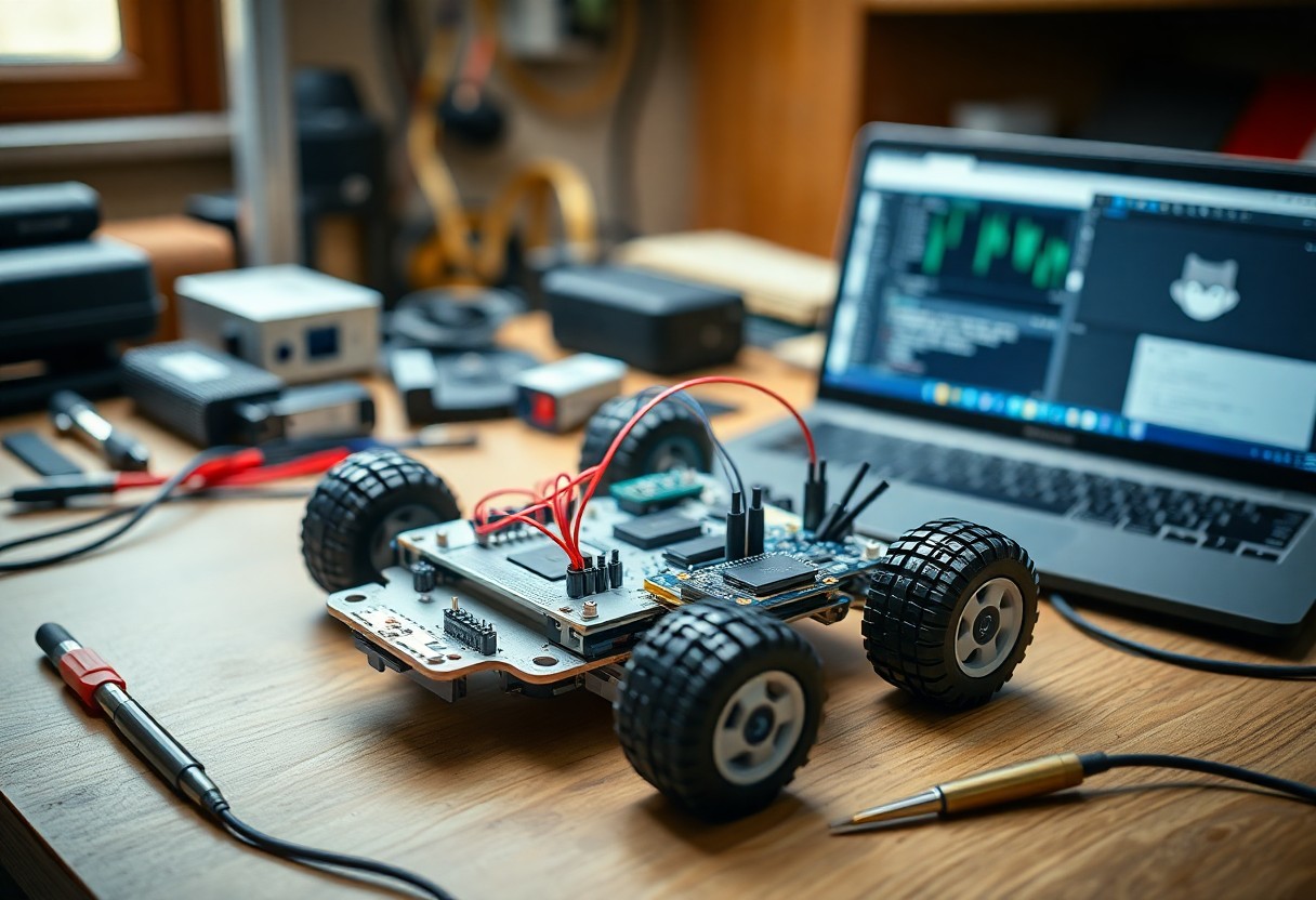
There’s a straightforward way to build your own robot using open-source hardware. You can access affordable, customizable components and detailed schematics online. With basic tools and clear instructions, you assemble, program, and test your robot efficiently. This guide walks you through each step with precision and clarity.
Selecting the Right Open-Source Platform
Choosing the right open-source platform shapes your robot’s capabilities and development speed. You need a balance between processing power, community support, and expandability. Platforms differ in programming environments, power efficiency, and peripheral compatibility. Your project’s complexity and intended functions guide this decision. Recognizing the long-term maintenance and upgrade path ensures sustained progress.
Critical Factors for Choosing Microcontrollers
Performance needs define which microcontroller fits your robot. Consider clock speed, available GPIO pins, memory size, and power consumption. Some projects demand real-time responses, while others prioritize wireless connectivity. Built-in features like ADCs or PWM outputs reduce external components. Recognizing these factors prevents bottlenecks during development.
- Processing speed and core architecture
- Number and type of I/O pins
- Onboard memory (RAM and flash)
- Power requirements and sleep modes
- Supported communication protocols (I2C, SPI, UART)
Comparing Arduino, Raspberry Pi, and ESP32 Ecosystems
Different platforms serve different robotic needs. Arduino excels in simple, real-time control tasks. Raspberry Pi offers full Linux computing for vision or AI workloads. ESP32 bridges both with built-in Wi-Fi and Bluetooth at low cost. Your choice depends on required interfaces and software flexibility.
| Arduino | Best for beginners, real-time sensor control, minimal setup |
| Raspberry Pi | Runs Linux, supports Python/C++, ideal for cameras and AI |
| ESP32 | Wi-Fi/Bluetooth enabled, low power, great for IoT-connected robots |
Arduino uses a simplified C++ environment, making it accessible for quick prototyping with sensors and motors. Raspberry Pi supports complex software stacks, enabling voice recognition or computer vision through libraries like OpenCV. ESP32 operates efficiently in wireless applications, offering dual-core processing and deep sleep modes for battery-powered builds. Each ecosystem has extensive community libraries and pin-compatible modules that accelerate development.
| Programming Language | Arduino: C/C++; Raspberry Pi: Python, C++, JavaScript; ESP32: C/C++, MicroPython |
| Connectivity | Arduino: Add-ons required; Raspberry Pi: Ethernet, Wi-Fi, Bluetooth; ESP32: Built-in Wi-Fi and Bluetooth |
| Real-Time Performance | Arduino: Excellent; Raspberry Pi: Limited by OS; ESP32: Good with RTOS support |
| Power Efficiency | Arduino: Low; Raspberry Pi: High consumption; ESP32: Optimized for low-power use |
| Community & Libraries | All three offer strong support, but Arduino leads in beginner tutorials |
Sourcing Core Hardware Components
Every robot begins with reliable parts you can trust. Start by selecting a compatible microcontroller like Arduino or Raspberry Pi, then pair it with motor drivers and a chassis that match your design goals. Open-source communities often share tested component lists-use them to avoid common pitfalls. Stick to reputable suppliers to ensure consistency and support.
Tips for Procuring Quality Sensors and Actuators
Choose sensors and actuators based on your robot’s environment and tasks.
- Look for modules with open datasheets and active community support
- Test sample units for responsiveness and durability before bulk buys
- Prefer standardized interfaces like I2C or GPIO for easier integration
Knowing what real-world conditions your robot will face helps you pick components that perform consistently over time.
Evaluating Power Supply and Battery Requirements
Your robot’s performance depends heavily on stable power delivery. Calculate total current draw from all components and select a battery with sufficient voltage and capacity. Consider rechargeable lithium-ion or LiPo packs for balance between weight and runtime. Always include a voltage regulator to protect sensitive electronics.
Power needs vary widely depending on motor load, sensor usage, and processing demands. A small wheeled robot might run on a 7.4V 2200mAh pack, while larger builds with servos or vision systems require higher amperage and redundancy. Include a power meter in your setup to monitor consumption during testing. This helps identify power-hungry components and optimize efficiency before final deployment.
Structural Assembly and Design
Designing your robot’s frame begins with selecting modular, open-source components that ensure adaptability and strength. You can follow the Open Source Delta Robot: 5 Steps guide for inspiration on precision and scalability in 3D-printed joints and linkages.
How-to Build a Durable Modular Robot Chassis
Start with aluminum extrusions or 3D-printed brackets that allow quick reconfiguration. Your chassis must support added sensors and actuators while maintaining balance. Use standardized fasteners to simplify future upgrades and repairs across different builds.
Integrating Drive Systems and Motor Controllers
Mount your motors securely to the chassis using compatible brackets and align wheels or tracks for smooth motion. Connect each motor to an open-source controller like an Arduino-based shield, ensuring wiring follows polarity standards to prevent damage during testing.
Matching motor controllers to your drive system ensures efficient power delivery and responsive control. Choose drivers such as the L298N or VNH5019 based on voltage and current needs. Configure them with open-source firmware to enable precise speed and direction adjustments through your main microcontroller, allowing real-time adaptability in dynamic environments.
Circuitry and Electronic Integration
Your robot’s functionality hinges on well-executed circuitry and electronic integration. Connect sensors, motors, and microcontrollers using a breadboard or custom PCB, ensuring power requirements are matched and signal paths are clean. Use open-source design tools like KiCad or Fritzing to map connections accurately and test each subsystem before final assembly.
Best Practices for Schematic Design and Layout
Clarity defines a strong schematic. Label every component clearly, group related circuit blocks together, and use consistent symbols from trusted libraries. Avoid overlapping wires and maintain logical signal flow from left to right. After finalizing your design, double-check connections against datasheets to prevent errors.
Soldering Tips for Secure and Reliable Connections
Heat applied correctly ensures lasting joints. Use a temperature-controlled iron, clean the tip frequently, and apply solder to the joint-not the iron. Work in a well-ventilated space with the right gauge wire and avoid cold joints. After soldering, inspect each connection under light for shine and conical shape.
- Use flux to improve solder flow and joint quality
- Hold components securely with a third-hand tool
- Trim excess leads after soldering to reduce shorts
- Allow joints to cool naturally without disturbance
After completing your soldering, test continuity with a multimeter to confirm solid electrical paths and rule out unintended bridges.
Software and Firmware Implementation
Every robot needs instructions to act, and that begins with well-structured code. You’ll use open-source firmware like Arduino or MicroPython to bring your hardware to life. These platforms support real-time control and integrate easily with sensors and motors. Your robot’s behavior starts here-through logic, timing, and responsiveness.
How-to Configure the Development Environment
You’ll need the right tools installed before writing a single line. Download the IDE that matches your microcontroller-Arduino IDE for AVR boards or Thonny for Raspberry Pi Pico. Install drivers if required, then verify communication by uploading a simple blink sketch. A working setup ensures smooth progress into actual coding.
Coding Basic Movement and Logic Loops
Your robot moves when code sends signals to motor drivers. Start by defining forward, backward, and turn functions using PWM outputs. Wrap these in a loop that runs continuously, checking sensor inputs each cycle. This creates responsive, autonomous behavior based on real-time conditions.
Writing movement logic means breaking actions into small, repeatable steps. Use a main loop that polls sensors, evaluates thresholds, and triggers motor responses accordingly. For example, if an ultrasonic sensor detects an obstacle under 20 cm, the robot stops and turns right. Timing matters-use non-blocking delays like millis() so your robot stays aware of its surroundings. Keep functions modular so you can reuse them in more complex routines later.
System Optimization and Troubleshooting
Efficient robot performance depends on fine-tuning both software logic and hardware responsiveness. You’ll want to minimize latency between sensor input and actuator output while ensuring power consumption stays within safe limits. Regular testing under real-world conditions reveals hidden inefficiencies that simulations often miss. This leads to more reliable field operation.
Factors Influencing Sensor Calibration and Accuracy
- Environmental temperature shifts can alter sensor baseline readings
- Electromagnetic interference from motors affects signal integrity
- Physical mounting misalignment introduces measurement drift
- Power supply noise impacts analog sensor precision
Each of these conditions alters how your sensors interpret real-world data. This demands routine recalibration and shielding strategies to maintain consistent performance.
Debugging Common Hardware Communication Issues
Intermittent signals between microcontrollers and peripherals often stem from mismatched baud rates or loose wiring. You may notice garbled serial output or unresponsive I²C devices during initial tests. This typically resolves with proper pull-up resistors and protocol timing verification.
Start by confirming that all devices share a common ground and operate at compatible voltage levels. Use a logic analyzer or serial monitor to inspect data packets for expected headers and checksums. If an I²C device doesn’t respond, scan the bus to verify its address hasn’t changed due to configuration shifts. This hands-on inspection often uncovers subtle wiring faults or firmware mismatches that prevent stable communication.
Final Words
Taking this into account, building a robot with open-source hardware puts powerful tools in your hands. You access transparent designs, reduce costs, and adapt systems to your exact needs. By using community-supported platforms, you solve problems faster and refine your skills through real-world testing. Your project grows not from isolated effort but shared knowledge and proven components.