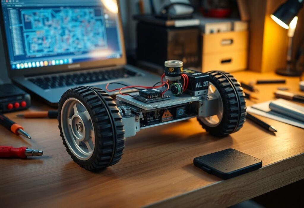
Most self-balancing robots rely on precise sensor feedback and real-time control, and you can build one using an Arduino, a motor driver, MPU-6050 gyroscope, and DC motors. With basic coding and electronics skills, you’ll assemble and program a robot that maintains balance on two wheels by continuously adjusting motor output based on tilt data.
Essential Hardware Selection
Choosing the right components sets the foundation for a stable self-balancing robot. You’ll need a responsive microcontroller, accurate IMU, suitable motors, and a reliable power source. Each part must work in harmony, ensuring real-time data processing and precise motor control to maintain upright balance under dynamic conditions.
Selecting the Microcontroller and IMU
Your microcontroller processes sensor data and drives motor responses in milliseconds. An Arduino Uno or ESP32 works well for beginners, offering sufficient processing power and community support. Pair it with a reliable MPU-6050 IMU, which combines a 3-axis accelerometer and gyroscope for accurate tilt detection.
Motor Specifications for Balance Stability
Small DC motors with encoders provide the responsiveness needed for balance control. Look for gear motors with a high torque-to-size ratio and RPMs between 100-200. These specs allow quick corrections without overshooting, keeping your robot upright during disturbances.
High-resolution encoders give you precise feedback on wheel position and speed, enabling tight control loops. Without accurate feedback, even fast motors can’t correct tilt effectively. Choose motors with built-in 1000 PPR encoders or higher to ensure smooth, stable balancing across flat and slightly uneven surfaces.
Designing the Physical Chassis
Your robot’s stability begins with a well-thought-out chassis. Position components symmetrically and keep heavy elements low to enhance balance. A compact layout improves responsiveness and reduces sway during motion.
Structural Factors Influencing Center of Gravity
Height and placement of components directly affect balance.
- Mount the battery at the lowest point
- Align motors symmetrically under the main board
- Keep the microcontroller near the central axis
Recognizing how mass distribution impacts tilt response ensures smoother self-correction.
Assembly Tips for Rigid Frame Construction
Use materials that resist flex under dynamic loads.
- Choose aluminum or acrylic over flimsy plastics
- Reinforce joints with metal brackets
- Pre-tighten screws before final calibration
This minimizes unwanted movement during operation.
Stiffness in the frame prevents misalignment of sensors and motors during balancing. Even slight bending can throw off gyroscopic readings and delay corrective actions.
- Double-layer mounting plates add stability
- Use spacers to maintain alignment between layers
- Avoid adhesive-only joints for load-bearing parts
This ensures long-term reliability and precise control under real-world conditions.
Implementing the PID Control Algorithm
You’ll use sensor data to calculate the robot’s tilt angle and adjust motor output accordingly. The PID algorithm processes this error signal-difference between desired and actual angle-through proportional, integral, and derivative terms. This real-time correction keeps the robot upright by responding to both current and past tilt behavior.
Tuning Factors for Proportional and Integral Gains
Start by increasing the proportional gain until the robot responds quickly to tilt without excessive oscillation. Then, add a small integral gain to eliminate steady-state error over time.
- Too much proportional gain causes violent shaking
- Excessive integral gain leads to overshoot and drift
Assume that your environment is stable and sensor noise is minimal during tuning.
How-to Calibrate the Inertial Measurement Unit
Place your robot on a flat, motionless surface before powering it on. This allows the IMU to establish baseline readings for acceleration and angular velocity. Accurate calibration ensures the tilt angle fed into the PID loop reflects real orientation, minimizing drift and false corrections during operation.
Calibrating the IMU involves collecting offset values for each sensor axis over several seconds. The microcontroller averages these readings to determine zero-g and zero-rate biases. Without this step, even minor sensor inaccuracies compound over time, leading to unstable balance. Always recalibrate if you notice gradual leaning or jitter when stationary.
Software Development and Logic
Code transforms your robot from a collection of parts into a responsive machine. You’ll rely on sensor data to make real-time decisions, primarily using the gyroscope and accelerometer readings from the IMU. Your microcontroller runs a continuous loop that calculates tilt angle and adjusts motor output accordingly. Precision in timing and logic ensures stable, upright motion.
Writing the Core Balancing Loop
Your robot stays upright through a tight feedback cycle. The loop reads IMU data, computes the current angle using a filter like Complementary or Kalman, then applies a control algorithm-typically PID-to determine motor direction and speed. This cycle repeats hundreds of times per second, correcting imbalance before it grows.
Advanced Tips for Real-time Optimization
Efficient timing keeps your control loop consistent. Use non-blocking functions and fixed time intervals to avoid jitter. Prioritize sensor reading accuracy and minimize computation overhead by simplifying math where possible. These small gains add up to smoother, more stable balancing under real-world conditions.
- Use a fixed time step for your loop (e.g., 5ms) to ensure consistent PID calculations
- Pre-calculate constants to reduce runtime math
- Limit serial debugging during operation to avoid timing delays
- Optimize IMU read frequency to match control loop speed
| Technique | Impact on Performance |
|---|---|
| Fixed Time Step Loop | Improves PID stability and response predictability |
| Precomputed Constants | Reduces CPU load and prevents calculation lag |
| Minimal Serial Output | Prevents blocking delays in real-time execution |
| Optimized IMU Sampling | Ensures timely, accurate angle updates without overflow |
Real-time performance hinges on disciplined code structure. Your robot doesn’t have the luxury of delayed reactions-every millisecond counts. Focus on reducing variability in loop execution time. Replace floating-point operations with integers where precision allows, and use direct register access if your platform supports it. These refinements make the difference between shaky operation and smooth, confident balance.
Troubleshooting and Refinement
Perfecting your self-balancing robot often takes persistence and careful observation. Small imbalances in code or hardware can prevent stable operation, so systematic testing is key. You’ll want to isolate variables, adjust parameters incrementally, and validate each change with real-world testing to achieve smooth, autonomous balance.
Identifying Common Mechanical Failures
Wobbly performance may stem from loose joints or misaligned wheels. You should inspect all mounting points and ensure the center of gravity aligns directly over the axle line. Even slight shifts in weight distribution can destabilize the system, so secure every component firmly and retest after each adjustment.
Software Debugging for Signal Noise
Noisy sensor readings disrupt balance by feeding inaccurate tilt data to the controller. You might notice erratic motor behavior or sudden jerks. Filtering the raw IMU output with a complementary or Kalman filter smooths the signal and improves stability, allowing the robot to respond more accurately to actual movement.
Signal noise often originates from electrical interference or poor sampling rates. You can reduce it by placing capacitors across motor terminals, using shielded cables for sensors, and ensuring your IMU updates at a consistent frequency. Monitor the serial output in real time to catch anomalies and fine-tune filter constants until the robot maintains steady posture without oscillation.
To wrap up
With these considerations, you now have the foundational knowledge to build a self-balancing robot from scratch. You understand the mechanics, electronics, and control logic required. By applying precise sensor feedback and proportional-integral-derivative tuning, you achieve stability. Your hands-on implementation determines success-start simple, test continuously, and refine your design iteratively.